Radar Transceiver
ASIC Success Story
Application
To improve target detection accuracy, advanced radar systems can use a phased array of antennas. By precisely controlling individual antennas within an array, the emitted electromagnetic waves can be manipulated to create constructive interference, thus boosting the overall signal strength. By adjusting the phase relationship between the array of antennas, the signal can also be electronically “steered” to a point in different directions without the need to physically move the antennas.
This “beamforming” technique is especially useful in radar systems as it reduces the signal radiated in some directions while boosting it in the direction of interest. Consequently, the system’s accuracy is significantly improved. Furthermore, the dwell time, no longer limited by the rotation speed of a dish, is freely selectable and higher-quality images can be produced in the area of interest.

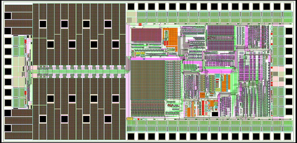
Custom Solution from CSS
This ASIC is part of an advanced phased array radar system controller. It provides Phase & Attenuation data and controls transmit and receive power to two Monolithic Microwave Integrated Circuit (MMIC) RF amplifiers.
Communication between the ASIC and system is via a 22-bit SPI that includes 4 bits of CRC for error detection. An internal EEPROM stores receive & transmit calibration data for 4 frequency and 4 temperature ranges. Phase and attenuation data is calculated by an internal math processor. It performs 12-bit multiplication and addition/subtraction operations.
The status of twenty-two internal voltages, currents and temperatures is monitored by a 10-bit ADC. Each parameter is compared to programmable limits and an error flag is signaled to the system if any of the system parameters fall outside acceptable limits.
Key Features
- 10-bit SAR ADC with 22-channel Analog MUX
- Automatic error flag generation
- SRAM and EEPROM
- 6-channel Power FET with 50 mOhm and 200 mOhm R-on
- Power-on Reset
- Low Voltage Detector
- Math Processor Unit
- 22-bit SPI with 4-bit CRC
- Dual Port & Bi-directional CMOS along with LVPECL & LVDS
- Temperature Detector
- Temperature Range = -40°C to +85°C