6-Axis Inertial Motion Unit
ASIC Success Story
Application
A 6-axis inertial measurement unit (IMU) is a device that reports linear and rotational acceleration and can be used for navigation control of various land and air vehicles. Such systems can provide accurate navigation information in environments where GPS is not available.
Accelerometers are used to sense acceleration in three linear axes and gyroscopes are used to sense acceleration in three rotational axes. These highly accurate IMUs tend to be bulky and heavy. On the other hand, IMUs can be built from microelectromechanical (MEMs) devices with incredible improvements in size and weight, but historically the accuracies were only suited to consumer products (e.g., free fall detection or orientation sensing in a cell phone).
Recent advances in MEMs technologies as well as the interfacing microelectronics promise to provide sufficient accuracy in a 6-axis MEMs IMU to be used as a navigation system.
CSS partnered with a leading defense company to design interface ASICs for both the Accelerometer and Gyroscope MEMs devices that realize an IMU sensor suitable for navigational purposes.

Custom Solution from CSS
The Gyro ASIC provides the electrical interface to a MEMS gyro. It has 5 total transmit paths, 2 receive paths, and a variety of integrated support functionality.
The transmit paths include a single-ended high voltage carrier path at approximately 100 KHz, 2 high-voltage DC-biasing differential pickoff paths, and 2 high-voltage differential AC forcing paths at up to 25 KHz.
The two differential receive paths measure the AC-coupled gyro response from each pickoff node.
Support circuitry includes a bandgap, reference generator, POR, fuse memory for trimming and chip ID, temperature sensor(s), and I/O interfaces for register control and data paths to an external micro-controller.
The Accelerometer ASIC provides four channels of high-voltage MEMS drivers as well as the analog signal processing circuits.
This ASIC showcases CSS’s ability to combine low-noise precision analog, including a 14-bit ADC, with high-voltage precision switches.
The ASIC also contains trimming functions, power-management for the MEMs device, as well as serial communications.
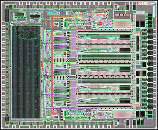
Key Features – Gyroscope ASIC
- 16-bit 3rd order Sigma Delta ADCs (x2) Fmod=16MHz, Fsamp=1MHz, Fsig=65-135 KHz
- 16-bit 3rd order Sigma Delta DACs (x5) Fmod=16MHz, Fsamp=1MHz, Fsig=0 to 135 KHz
- HV transmit amps (+/- 9V)
- AC-coupled RX LNA (TIA) with capacitive feedback and large common-mode accommodation (x2)
- SPI register interface
- 1.8V synthesized digital data paths
- Input interpolators 1->16 MSpS (0, 1st, and 2nd order)
- Output decimation filters 16->1 MSpS (3rd order)
- Data framing and serial interface
- Chopped bandgap and bias reference generation block
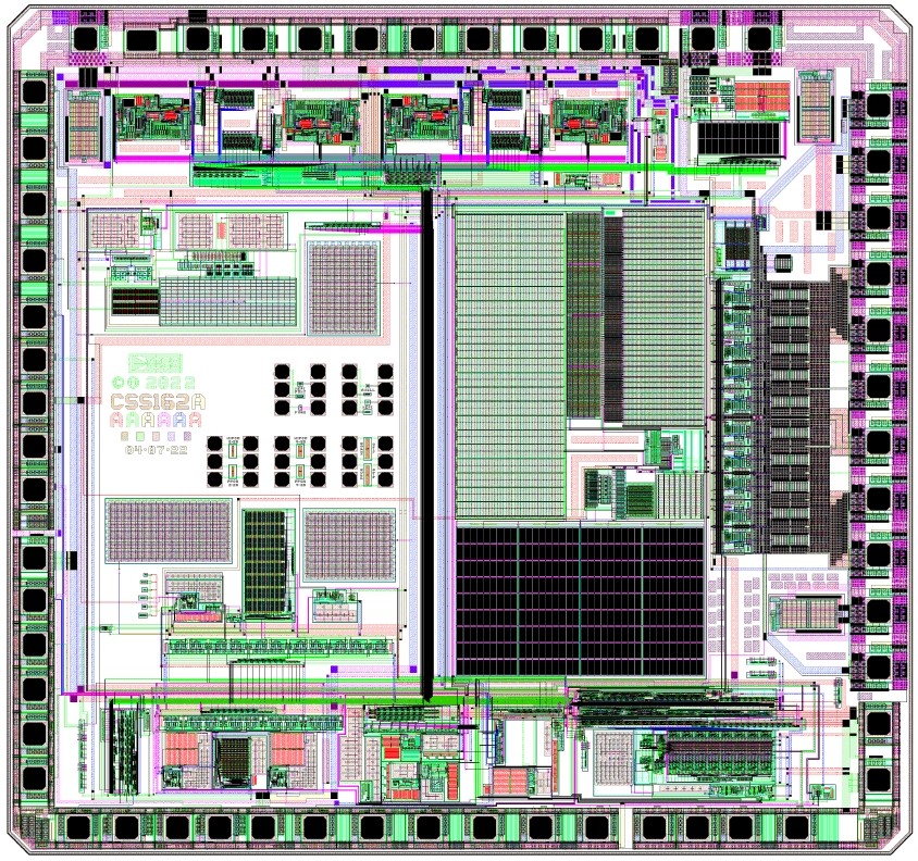
Key Features – Accelerometer ASIC
- Supply voltages = ±4.0V, +34V
- 3 Internal LDO regulators provide ±3.3V and 16V to 32V voltage supplies
- Low Noise signal channel
- 4 Independent HV MEMS Drivers
- Internal Voltage Reference & IBIAS Generator with OTP trim
- 25MHz SPI Serial Interface
- 8-bit DAC for offset adjust
- 14-bit SAR ADC